
tube placed  at  the  center (fig. 2).  This  type of tuned  circuit has
several advantages.   A quarter-wave circuit would normally be preferred
because of its greater  bandwidth, but I wanted to use easily obtainable
standard copper water pipe as the center  conductor  of the transmission
line tank circuit. The resulting high-impedance  transmission line would
make a quarter-wave plate tank circuit physically short and difficult to
handle.
      In addition, the heavy rf current that flows on the tube seals and
control grid would, in the process of charging up the output capacitance
to the plate voltage swing,  tend to concentrate on one side of the tube
if a  single-ended  quarter-wave  circuit  were used.  This current con-
centration  would cause  localized  heating of the tube.  The best tuned
circuit configuration to minimize this effect is a symmetrical cylindar-
ical coaxial cavity.  Unfortunately,  this type of cavity is complex and
difficult to build.

      A practical compromise is to use two quarter-wave lines connecting
to opposite sides of the tube.  It is  interesting  to note that each of
the two quarter-wave lines is physically longer than if only one quarter
wave line were used.  This is  because  only one-half of the tube output
capacitance loads each of the two lines.
fig. 3. Variable plate portion of plate-tuning capacitor C3. This arrangement permits the
capacitor to be adjusted under full power without "jumpy" tuning as there are no moving or
sliding contacts which carry heavy rf current.
fig. 4. Details of plate lines L5 and L6. Copper tubes are standard water pipe.
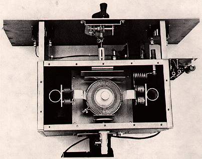
Resonance is established by a moving plate capacitor (C5); antenna
loading is accomplished by a second capacitor (C6) placed at the anode
of the 8877. Output power is coupled from the plate circuit through the
series capacitor into a 50-ohm output. In the top-view photo tuning cap-
acitor C5 is at the front of the compartment; variable loading capacitor
C6 is at the rear. The plate choke is visible in the front corner.
construction
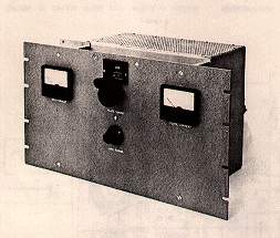
The two-meter amplifier is built in an enclosure measuring 10 1/4
X 12 X 6 1/4 inches. The 8877 socket is centered on a 6 X 6 subchassis
plate. A centrifugal blower forces cooling air into the under-chassis
area; the air escapes through the 2-5/8-inch diameter socket hole.
The plate tuning mechanism is shown in fig. 3. This simple
apparatus will operate with any variable plate capacitor, providing a
back and forth movement of about one inch.It is driven by a counter dial
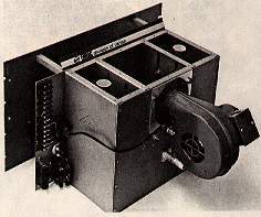
Rear of amplifier showing blower and coaxial output connector. Amplifier is upside down
in this photograph.
and  provides  a  quick  inexpensive  and  easy  means  of driving a vhf
capacitor.  The ground return path for the  grounded  capacitor plate is
through a wide low-inductance beryllium-copper or brass shim stock which
provides spring tension for the drive mechanism.
fig. 5. Anode clamp assembly for the two-meter linear amplifier.
      The variable output  coupling  capacitor is located at the side of
the 8877 anode. The type-N coaxial fitting is connected to the  moveable
plate  of the coupling capacitor.  The fitting is  centered in a special
tubular  assembly which allows the wole connector to slide in and out of
the  chassis,  allowing the  variable plate of the coupling capacitor to
move with respect to the  fixed plate  mounted on the tube anode  clamp.
When the  final  loading  adjustment has been set the sliding fitting is
clamped by an arrangement similar to the slider on a variable wire-wound
resistor.
      The length  of the plate-line inductors (L5 and L6) is adjusted by
means of dural  blocks  placed at the  shorted end of the line (fig. 4).
The position of the blocks is determined by setting capacitor C5  at its
lowest  value  and  adjusting  line  lengths  so that  the plate circuit
resonates at 148 MHz with the 8877 in the socket.
      The plate rf  choke is  mounted  between the junction of one plate
strap  and a pair  of the  dual  blocking  capacitors;  the high-voltage
feed-through  capacitor  is  mounted  to the  front  wall  of  the plate
compartment.  The  blocking  capacitors  are  rated for  rf service, and
inexpensive tv-type  capacitors  are not recommended for this amplifier.
A short chimney to  direct cooling air from the socket through the anode
of the 8877 is made from Teflon and clamped between the chassis deck and
the anode strap.*

operation
      Amplifier  operation  is completely stable with no parasitics. The
unit  tunes  up  exactly  as if  it were on the "dc bands."  As with all
grounded-grid amplifiers excitation should never be applied  when  plate
voltage is removed from the amplifier.
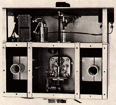
Underchassis view of the two-meter amplifier. The cathode input circuit he center
compartment. Plate lines are visible in the side compartments.
      The first step is to grid-dip  the  input  and  output circuits to
near-resonance with  the 8877  in  the socket.  A  swr  meter  should be
placed  in  series  with  the  input  line  so  the input network may be
adjusted for lowest swr.
      Tuning  and  loading  follows  the  same  sequence as any standard
grounded-grid amplifier. Connect a swr indicator at the output and apply
a small amount of rf drive. Quickly tune the plate circuit to resonance.


table 1. Performance data for the 144-MHz power amplifier under the conditions
most suitable for amateur ssb (2000 watts PEP) and cw (1000 watts).

             Plate voltage                    3000 V         2500 V           2500 V
             Plate current (single tone)       667 mA         800 mA         400 mA
             Plate current (idling)             54 mA          44 mA          44 mA
             Grid voltage                      -12 V          -12 v          -12 V
             Grid current (single tone)         46 mA          50 mA          28 mA
             Power input                      2000 W         2000 W         1000 W
             Power output                     1240 W         1230 W          680 W
             Efficiency (apparent)              62 %           62 %           68 %
             Drive power                        47 W           67 W           19 W
             Power gain                       13.8 dB        12.6 dB        15.5 dB


The cathode circuit should now be resonated. The swr between the exciter
and the amplifier will not necessarily be optimum.  Final  adjustment of
the cathode circuit for  minimum  swr  should  be  done  at  full  power
because the input impedance  of a cathode-driven amplifier is a function
of the plate current of the tube.
      Increase the rf  drive  in  small  increments  along  with  output
coupling until the  desired  power  level  is reached.  By adjusting the
drive and loading together it will be possible to  attain  the operating
conditions given in  the performance chart in  table 1.  Always tune for
maximum plate efficiency:  maximum output power for minimum input power.
It is quite easy to load  heavily  and  underdrive  to  get  the desired
power input but power output will be down if this is done.
     I would like to thank K6DC for his help in adjusting  and determin-
ing the operating conditions of this two-meter amplifier.

*Detailed drawings of the anode clamp, plate resonator and blocking capacitor assembly,
and variable plate tuning capacitor (C5) are available from R. Sutherland, EIMAC
Division of Varian, 301 Industrial Way, San Carlos, Califirnia 94070. Ask for drawing
numbers 168658, 168648, and 168647.

references

1. R. Sutherland, W6UOV, "Two Kilowatt Linear Amplifier for Six Meters,"
   Ham Radio, February, 1971, page 16.
2. R. Barber, R Rinaudo, W. Orr, R. Sutherland, " Modern Circuit Design for VHF Transmitters,"
   CQ, November, December, 1965.
ADDENDUM
This circuit may be substituted for the hard to find 1N3311 zener biasing diode shown in the schematic circuit of fig.1
Mount the 2N3055 on a TO3
style heatsink using insulating hardware.