The W5UN Quagi 97 is a computer optimized quagi derived from the original W5UN Quagi of the early 1980s. The length of the 1997 model has been deliberately shortened to allow it fit on a 24 foot boom. Performance is substantially higher than that of the original antenna. It now compares favorably with yagis of the same length. The two programs used to optimize the updated antenna were AO6 and NEC 2.
This antenna has not been verified by actual
construction. Gain and front to back will be as stated below. The
only component of the antenna that needs verification is the 50
ohm match. Who would like to be the FIRST to build the actual
prototype model?? Full consultation will be available to the
prototype builder during construction. Contact w5un@wt.net if you wish to be the
first!
Antenna Characteristics:
23' 9"
11 Element Gain: 13.56 dBd at 144.100 Mhz
F/B : 23 dB Stacking: Optimum: E Plane: 13.73'
Optimum: H Plane: 12.86'
Stacking can be reduced up to 90 percent of optimum and still
achieve acceptable stacking gain. Optimum stacking is
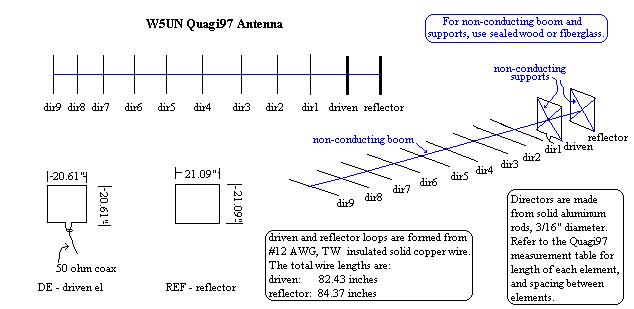
recommended, however. W5UN QUAGI 97 Dimensions in FREE SPACE:
Element     Boom Pos.    El. Length    Material
Reflector    0.0000"     84.37" loop.  #12 solid INSULATED copper wire *
Driven      16.2500"     82.43" loop.  #12 solid INSULATED copper wire *
Dir 1       37.1875"     36.168"       3/16" aluminum rod
Dir 2       70.1875"     36.052"       3/16" aluminum rod
Dir 3      102.5000"     35.817"       3/16" aluminum rod
Dir 4      135.8125"     35.475"       3/16" aluminum rod
Dir 5      169.0625"     35.179"       3/16" aluminum rod
Dir 6      202.8125"     35.090"       3/16" aluminum rod
Dir 7      234.2500"     35.324"       3/16" aluminum rod
Dir 8      264.8750"     35.617"       3/16" aluminum rod
Dir 9      285.0000"     35.108"       3/16" aluminum rod
* #12 TW insulated solid copper wire is common house wire, found at most hardware and building supply stores. Do not strip the insulation.
The above dimensions may be used for non metallic booms like wood or fiberglass.
If you wish to use a metal boom with through the boom insulated elements, please apply the following correction to the directors only. The reflector and driven quad elements must remain insulated from the boom.
Boom Diameter           Correction               Add
0.750" or 19.050MM        10.56%          .0792" or  2.02MM
0.875" or 22.225MM        12.14%          .1062" or  2.70MM
1.000" or 25.400MM        13.66%          .1366" or  3.47MM
1.125  or 28.575MM        15.13%          .1702" or  4.32MM
1.250" or 31.750MM        16.54%          .2068" or  5.25MM
1.375" or 34.925MM        17.90%          .2462" or  6.25MM
1.500" or 38.100MM        19.21%          .2882" or  7.32MM
1.750" or 44.450MM        21.67%          .3792" or  9.63MM
2.000" or 50.800MM        23.91%          .4783" or 12.15MM
                                                             (End of Table)
Further information concerning use of metallic booms with insulated 'thru-the boom' mounted elements follows:
PROVEN ACCURATE FOR BOOM DIAMETERS
SMALLER THAN .055 WAVELENGTHS.
MEASUREMENTS BY DL6WU.FORMULA BY G3SEK.
FORMULA: C = 12.5975B - 114.5B^2
C = CORRECTION FACTOR AS A FRACTION OF THE BOOM DIA.
B = BOOM DIA IN WAVELENGTHS
B^2 MEANS B SQUARED
2 METERS
BOOM DIAMETER CORRECTION ADD
2 METERS.
0.750" OR 19.050MM 10.56% .0792" OR 2.02MM
0.875" OR 22.225MM 12.14% .1062" OR 2.70MM
1.000" OR 25.400MM 13.66% .1366" OR 3.47MM
1.125 OR 28.575MM 15.13% .1702" OR 4.32MM
1.250" OR 31.750MM 16.54% .2068" OR 5.25MM
1.375" OR 34.925MM 17.90% .2462 OR 6.25MM
1.500" OR 38.100MM 19.21% .2882" OR 7.32MM
1.750" OR 44.450MM 21.67% .3792 OR 9.63MM
2.000" OR 50.800MM 23.91% .4783" OR 12.15MM
20.000MM 11.04% 2.21MM
28.000MM 14.87% 4.16MM
30.000MM 15.78% 4.73MM
32.000MM 16.66% 5.33MM
38.000MM 19.17% 7.29MM
Insulators can be commercial shoulder insulators and keepers or
as simple as
heat shrink tubing with the element held in place by hot melt
glue or epoxy
glue.